
In fields such as powder processing, mineral separation, and new energy material preparation, the classifier, as a core separation equipment, its precise separation capability directly determines product quality and raw material utilization rate. Centrifugal force is precisely the core power source for the classifier to achieve efficient and accurate separation. This article will deeply analyze the working mechanism of the classifier, reveal how centrifugal force drives materials of different particle sizes and densities to complete precise separation, and provide references for enterprises in equipment selection and process optimization by combining industry application scenarios.
I. Core Principle: The “Separation Logic” of Centrifugal Force and Force Balance
The essence of a classifier is to break the force balance of material particles by constructing a specific force field, making particles with different characteristics move along different trajectories and ultimately achieve separation. For centrifugal classifiers, the core logic is to use centrifugal force generated by high-speed rotation to amplify the force difference between particles of different sizes—which is also its key advantage distinguishing it from gravity classification and sieving classification.
According to mechanical principles, the magnitude of centrifugal force acting on particles in a centrifugal field can be calculated by the formula: F=mrω² (where F is centrifugal force, m is particle mass, r is rotation radius, and ω is angular velocity). It can be seen that centrifugal force is proportional to particle mass, rotation radius, and the square of angular velocity. In the fixed cavity of the classifier, the rotation radius r is relatively fixed; therefore, particle mass (approximately positively correlated with the cube of particle size) and angular velocity (i.e., classifier wheel speed) are the core variables determining the magnitude of centrifugal force.
When mixed materials enter the centrifugal field, particles of different sizes will form obvious force differences: coarse particles have large mass, and the centrifugal force they bear is much greater than the air drag (or liquid flow resistance), so they will be quickly thrown to the inner wall of the cavity; fine particles have small mass, and the centrifugal force is less than the air drag, so they will remain suspended with the air flow (or liquid flow) and move to the central area. This differentiation of motion trajectories based on centrifugal force differences is the core principle for the classifier to achieve precise separation.
II. Core Structure of Centrifugal Classifier: The “Hardware Foundation” Supporting Precise Separation
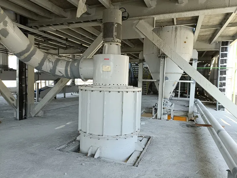
To ensure that centrifugal force stably exerts the separation effect, the classifier needs a reasonable structural design, and various components cooperate to construct a stable centrifugal field. Taking the most widely used turbo-type centrifugal classifier as an example, its core structure includes a drive device, classification rotor, feeding disc, casing, air flow control system, and collection system, each with its own functions:
-
Drive Device: Composed of a motor and a reducer, it provides adjustable rotating power for the classification rotor and is the “power core” for controlling the magnitude of centrifugal force. Through frequency conversion speed regulation technology, the rotor speed can be precisely adjusted, thereby controlling the classification accuracy (the higher the speed, the greater the centrifugal force, and the finer the particles that can be separated).
-
Classification Rotor: As the “generator” of the centrifugal field, it is the most critical core component of the classifier. It usually consists of upper and lower cage plates and dozens of uniformly distributed blades to form a cage structure, which forms a stable annular centrifugal field when rotating at high speed. The shape, spacing, and material of the blades directly affect air flow stability and classification efficiency; high-quality rotors can reduce eddy current interference and improve separation accuracy.
-
Feeding Disc: Located below the rotor, it is responsible for uniformly dispersing and throwing the materials to be classified into the classification area. If the materials are not evenly dispersed, local particle agglomeration will occur, directly affecting the classification accuracy. Therefore, the speed and structural design of the feeding disc need to be precisely matched with the feeding amount.
-
Casing and Air Flow Control System: The casing forms a closed classification cavity, and guide vanes or fairings are installed inside to stabilize the air flow direction and reduce turbulent losses; the air flow control system (including fans and guide vanes) generates a stable upward air flow, providing drag force against centrifugal force and carrying fine particles to the collection system. Some advanced equipment also introduces secondary air and tertiary air to enhance material cleaning and dispersion, further improving classification efficiency.
-
Collection System: Composed of cyclone separators, bag filters, discharge valves, etc., it collects fine particle products and coarse particle return materials (which can be returned to the mill to form a closed-circuit cycle) respectively, and realizes air purification and recycling, taking into account environmental protection and energy saving.
III. Precise Separation Process Driven by Centrifugal Force: Efficient Separation Completed in Four Steps
Based on the above structure, the separation process of the centrifugal classifier can be divided into four core steps: “feeding and dispersion—centrifugal separation—coarse-fine separation—product collection”, which is driven by the dynamic balance between centrifugal force and air drag throughout the process:
-
Material Feeding and Dispersion: The mixed powder to be classified enters the equipment through the feed inlet, is dispersed by the centrifugal force generated by the high-speed rotation of the feeding disc, and is uniformly thrown into the classification cavity to avoid particle agglomeration affecting the separation effect. At this time, the air flow entering from the bottom or surrounding area will carry the dispersed particles upward to form a gas-solid mixed flow.
-
Centrifugal Field Construction and Force Differentiation: The classification rotor rotates at high speed, forming a strong centrifugal field in the cavity. After the gas-solid mixed flow enters this area, the particles are immediately subjected to the combined action of centrifugal force and air drag: coarse particles, due to their large mass, have centrifugal force much greater than air drag, and their motion trajectory deviates toward the cavity wall; fine particles, due to their small centrifugal force, are “captured” by the air drag and move to the central area with the air flow.
-
Coarse-Fine Particle Separation: After the coarse particles are thrown to the inner wall of the machine shell, their speed decays rapidly, settles downward along the wall under the action of gravity, and finally is discharged through the coarse powder outlet at the bottom; the fine particles pass through the blade gaps of the classification rotor and enter the upper collection system with the air flow. Some equipment will “wash” the falling coarse particles through secondary air, bringing the mixed fine particles into the classification area again for re-separation, thereby improving the separation accuracy.
-
Product Collection and Air Circulation: After the fine particles enter the cyclone separator or bag filter with the air flow, due to the reduction of air flow speed, they settle and separate under the action of gravity to form qualified fine powder products; the purified air flow returns to the classification cavity (for recycling) or is discharged up to standard through the fan; the coarse particles can be returned to the front-end mill for re-grinding, realizing efficient utilization of raw materials.
IV. Centrifugal Force Regulation Skills: How to Achieve Precise Adaptation of Classification Accuracy?
In industrial production, the requirements for material particle size vary greatly among different industries (for example, new energy lithium battery cathode materials require a particle size distribution D50 ≤ 5μm, and cement industry coarse classification requires a particle size of 50-200μm). Through precise regulation of centrifugal force, flexible adaptation of classification accuracy can be achieved, with two core regulation methods:
-
Adjusting the Classification Wheel Speed: This is the most direct regulation method. The higher the speed, the greater the angular velocity ω, the stronger the centrifugal force, and the finer the particles that can be “screened”. For example, increasing the speed from 2000r/min to 4000r/min can reduce the classification threshold from 50μm to 20μm. At present, the speed adjustment accuracy of mainstream equipment can reach 1 revolution per minute, ensuring that the classification accuracy is stable within ±3μm, meeting the needs of high-end manufacturing.
-
Optimizing Air Flow Speed: Air flow speed determines the magnitude of drag force, forming a dynamic balance with centrifugal force. At the same speed, increasing the air flow speed can increase the drag force, allowing more fine particles to be carried, which is suitable for coarse classification needs; reducing the air flow speed can enhance the separation effect of centrifugal force and obtain finer products.

V. Industry Applications: Core Value Scenarios of Centrifugal Classifiers
With the precise separation capability driven by centrifugal force, centrifugal classifiers have been widely used in various fields and become key equipment for improving product quality:
-
New Energy Materials: In the production of lithium battery cathode materials and photovoltaic silicon materials, it is necessary to control the powder particle size within a strict range (such as cathode materials with D50 ± 0.5μm). Centrifugal classifiers can ensure uniform particle size distribution by precisely regulating centrifugal force, improving battery energy density and photovoltaic module efficiency.
-
Non-Metallic Mineral Deep Processing: In the high-value utilization fields of talcum powder, calcium carbonate, fly ash, etc., classifiers can classify the powder to more than 325 mesh, converting solid waste resources into high-value-added industrial raw materials. For example, classified fly ash can be used as cement admixture and concrete additive.
-
Pharmaceutical and Food Industries: In the production of pharmaceutical powders, milk powder, flour, etc., it is necessary to strictly control the particle size to ensure solubility and taste. Centrifugal classifiers can achieve hygienic classification, avoid metal contamination, and meet industry standards.
-
Chemical and Environmental Protection Industries: In the fields of fine chemicals and waste gas treatment, classifiers can separate and recover useful powder materials, reducing raw material waste and environmental pollution, such as the recovery and reuse of ultra-fine particles in chemical waste.
VI. Selection and Usage Points: Maximizing Centrifugal Separation Efficiency
When selecting a centrifugal classifier, enterprises need to focus on the following points in combination with material characteristics, production capacity requirements, and classification accuracy requirements:
-
Speed Adjustment Range: Priority should be given to equipment with a wide adjustable speed range and high adjustment accuracy to adapt to different particle size requirements;
-
Core Component Materials: Components such as the classification wheel and feeding disc need to be made of wear-resistant and corrosion-resistant materials (such as ceramics and wear-resistant steel) to extend service life and avoid material contamination;
-
Intelligence Level: Choose equipment equipped with an intelligent control system, which can real-time monitor parameters such as speed, air flow pressure, and particle size distribution, automatically adjust the operating state, and improve stability (such as continuous operation stability of more than 99.5%);
-
Energy Consumption and Environmental Protection: Pay attention to the unit processing energy consumption of the equipment (advanced equipment can reduce energy consumption by more than 30%), and ensure that the dust recovery rate of the collection system meets the standard (such as >99.4%) to comply with environmental protection regulations.
VII. Summary: Centrifugal Force is the “Core Engine” of Precise Separation
Centrifugal classifiers construct a strong centrifugal field through the drive device and achieve precise separation by utilizing the force difference between particles of different sizes. The core of their working mechanism is the dynamic balance between centrifugal force and air drag. Reasonable structural design, precise speed regulation, and air flow optimization are the keys to ensuring separation accuracy. With the rapid development of industries such as new energy, fine chemicals, and environmental protection, the precise separation capability of centrifugal classifiers will become an important support for enterprises to improve product competitiveness and reduce production costs.
If it is necessary to select a suitable centrifugal classifier according to specific material characteristics (such as particle size range, density, humidity) or optimize the existing classification process, it can combine the equipment’s speed adjustment range, energy consumption level, and intelligent functions to achieve dual improvement of production capacity and accuracy.
